


All Products
-
 BurookHi Norman... I just remembered i didn't let u know.... everything worked out we made both the wired and the remot control opening work... they loved the item (assuming it will hold its own for the next 10 years or so)
 -
 KiranYes I don’t doubt you. Jutai is one of the most confident companies I came across in China
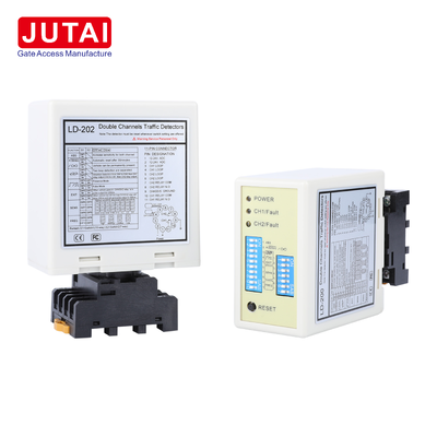
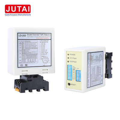
Dual Channel Vehicle Loop Detector with Two Loop Inputs Direction Detection and Relay Output for Parking Systems

| Place of Origin | China |
|---|---|
| Brand Name | JUTAI |
| Certification | CE |
| Model Number | LD-200 |
| Document | LD-200.202.pdf |
| Minimum Order Quantity | 1 |
| Price | Negotiation |
| Packaging Details | Cartoon |
| Delivery Time | 5 - 8 working days |
| Payment Terms | T/T,L/C,D/A,D/P,Western Union,Paypal,Alipay |
| Supply Ability | 1000 pieces per month |
Product Details
| Model | LD-200 / LD-202 | Loop Inputs | CH1 Loop + CH2 Loop |
|---|---|---|---|
| Frequency Range | 20-100kHz | Frequency Levels | High / Medium-High / Medium-Low / Low |
| Auto Reset Time | 10 Minutes In Normal Mode | LD-200 Power | 100-240VAC |
| LD-202 Power | 12-24VAC/DC | Sensitivity Range | 0.015% To 0.8% |
| Working Modes | 6 Selectable Modes | Sensitivity Levels | 8 Levels Per Channel |
| Detection Channels | 2 Channels | Direction Detection | Supported |
| Highlight | dual channel loop detector,vehicle loop detector with relay output,parking system loop detector |
||
Product Description
Dual Channel Vehicle Loop Detector with Direction Detection
This dual-channel vehicle loop detector is designed for parking systems requiring two road-loop inputs in one controller. CH1 and CH2 can monitor separate detection areas or be installed sequentially to evaluate vehicle crossing order for direction recognition and corresponding relay response.

Key Features
- Two independent inductive loop inputs: CH1 and CH2
- Vehicle direction recognition based on CH1/CH2 activation sequence
- Six selectable operating modes for different parking and traffic logic
- Eight sensitivity levels per channel (0.015% to 0.8%)
- Four selectable frequency bands (20-100kHz)
- Presence and pulse relay functions
- Automatic reset and permanent-presence operation
- Trailer sensitivity enhancement
- LED indication for power, detection status, and loop faults
How Direction Detection Works
For directional applications, two sensing loops are placed sequentially in the lane. Vehicle activation sequence (CH1→CH2 or CH2→CH1) determines travel direction. The selected working mode controls relay output generation for parking controller logic.
Technical Specifications
| Parameter | Specification |
|---|---|
| Product Type | Dual Channel Vehicle Loop Detector |
| Channels | 2 (CH1 + CH2) |
| LD-200 Supply | 100-240VAC |
| LD-202 Supply | 12-24VAC/DC |
| Sensitivity Range | 0.015%-0.8% |
| Frequency Range | 20-100kHz |
| Working Modes | 6 |
| Automatic Reset | Approx. 10 minutes in normal mode |
Typical Applications
Parking barrier entrance/exit lanes, vehicle access control systems, bidirectional parking lanes, two-zone vehicle presence detection, barrier passage confirmation, traffic-management and vehicle-flow logic.
Loop Installation Guidance
| Loop Perimeter | Recommended Turns |
|---|---|
| 3-4m | 6 turns |
| 4-6m | 5 turns |
| 6-10m | 4 turns |
| 10-20m | 3 turns |
| Above 20m | 2 turns |
Indicators and Switches
- Power LED (RED): Illuminates to indicate "Power ON"
- CH1 Detection LED: Steady On (vehicle detection), Slow Blinking (loop short circuit), Fast Blinking (loop open circuit)
- CH2 Detection LED: Steady On (vehicle detection), Slow Blinking (loop short circuit), Fast Blinking (loop open circuit)
Sensitivity Selection
Sensitivity and frequency adjustment via 7-way and 10-way dip switch settings with 8 different sensitivity levels available.
Switch Configuration
Comprehensive DIP switch configuration for sensitivity, frequency, and operational modes.
Reset Button Note: The LD-200 must be reset every time a setting change is made to the Dip switches.
Installation Guidelines
- Coil cutting size: rectangle, length 1.0-2.0 meters, width 0.8-1.2 meters
- Avoid right angles at corners
- Use ferromagnetic wires for induction coil (total length up to 500 meters)
- Keep product plug and socket in vertical direction during installation
System Integration
Ideal for single-channel entry/exit scenarios when integrated with JUTAI door controllers, gate barriers, RFID readers, and high-temperature resistance loop coils.
Working Principle
Comprehensive entry and exit processes with direction recognition functionality to prevent duplicate triggering and ensure accurate record keeping.
Independent Operation Mode
Can function as two independent single-channel loop detectors for cost-effective one-in/one-out parking lot configurations.
Recommended Products
-
VIDEO