


All Products
-
 BurookHi Norman... I just remembered i didn't let u know.... everything worked out we made both the wired and the remot control opening work... they loved the item (assuming it will hold its own for the next 10 years or so)
 -
 KiranYes I don’t doubt you. Jutai is one of the most confident companies I came across in China
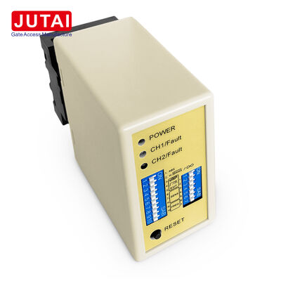
LD-200 Two Channel Parking Loop Detector with Direction Recognition Presence and Pulse Relay Outputs

| Place of Origin | China |
|---|---|
| Brand Name | JUTAI |
| Certification | CE |
| Model Number | LD-200 |
| Document | LD-200.202.pdf |
| Minimum Order Quantity | 1 |
| Price | Negotiation |
| Packaging Details | Cartoon |
| Delivery Time | 5 - 8 working days |
| Payment Terms | T/T,L/C,D/A,D/P,Western Union,Paypal,Alipay |
| Supply Ability | 1000 pieces per month |
Product Details
| Loop Inputs | CH1 Loop + CH2 Loop | Direction Detection | Supported |
|---|---|---|---|
| Auto Reset Time | 10 Minutes In Normal Mode | Power Supply | 100-240VAC |
| Frequency Range | 20-100kHz | Frequency Levels | High / Medium-High / Medium-Low / Low |
| Detection Channels | 2 Channels | Sensitivity Range | 0.015% To 0.8% |
| Independent Detection | CH1 And CH2 Independent Detection Supported | Working Modes | 6 Selectable Modes |
| Sensitivity Levels | 8 Levels Per Channel | Frequency Steps | 4 |
| Highlight | two channel loop detector,parking loop detector with relay outputs,loop detector with direction recognition |
||
Product Description
LD-200 Two Channel Parking Loop Detector with Direction Recognition
Product Overview

The LD-200 combines two parking-loop inputs with configurable relay logic for presence, pulse, and vehicle-direction applications. This detector is designed for barrier gates and parking-control cabinets where CH1 and CH2 require monitoring by a single device with different output behavior based on lane sequence.
The relay configuration is a key strength of this product. In independent mode, both channels function as separate vehicle-presence detectors. In pulse modes, the corresponding relay produces output when vehicles enter or leave loops. In directional modes, the detector uses CH1 and CH2 activation sequence to determine travel direction and generate programmed relay responses.
This makes the LD-200 ideal for installers needing one dual-channel detector to cover multiple parking functions instead of selecting different detectors for various lane designs.
Key Features
CH1 and CH2 inductive loop inputs
Presence relay operation
Pulse relay operation
Vehicle direction recognition
Six selectable working modes
Eight sensitivity settings per channel
20-100kHz adjustable frequency
Permanent vehicle presence mode
Approximately 10-minute automatic reset
LED indication for loop status and faults
Technical Specifications
| Parameter | Specification |
|---|---|
| Model | LD-200 |
| Primary Use | Parking barrier dual-loop detection |
| Number of Detection Zones | 2 |
| Loop Inputs | CH1 + CH2 |
| Power | 100-240VAC |
| CH1 Relay | COM / NO |
| CH2 Relay | COM / NO |
| Direction Detection | Configurable |
| Presence Mode | Configurable |
| Pulse Mode | Configurable |
| Selectable Modes | 6 |
| Sensitivity Levels | 8 each channel |
| Sensitivity Range | 0.015%-0.8% |
| Frequency | 20-100kHz |
| Frequency Steps | 4 |
| Auto Reset | Approx. 10 min in normal mode |
| Permanent Presence | Available |
| Trailer Mode | Sensitivity increase available |
Typical Applications
- Barrier opening request
- Vehicle presence monitoring
- Passage confirmation
- Entry/exit direction logic
- Two-zone detection
- Vehicle-flow signal generation
Loop Layout and Connection
For directional detection, two separate loops are aligned with the vehicle path and spaced approximately 1 meter apart. Loop turns are selected according to total loop perimeter. Installers should verify both loops separately, select suitable sensitivity, and choose different frequency settings when nearby loops create interference.
Indicators and Status
- Power LED (RED): Illuminates to indicate "Power ON"
- CH1 Detection LED:
- Steady On: Vehicle detection
- Slow Blinking: Loop short circuit or insufficient twists
- Fast Blinking: Loop open circuit or excessive twists
- CH2 Detection LED:
- Steady On: Vehicle detection
- Slow Blinking: Loop short circuit or insufficient twists
- Fast Blinking: Loop open circuit or excessive twists
Sensitivity Configuration
Sensitivity and frequency adjustment is facilitated through 7-way and 10-way dip switch settings:
- 8 different sensitivity settings available via dip switch configuration
- Dip switches 6, 7, and 8 govern CH1 sensitivity (0.8 to 0.015)
- Dip switches 3, 4, and 5 control CH2 sensitivity (0.8 to 0.015)
Switch Configuration
Switch 1 (S1) - Channel 1 Loop Function Selection:
- DIP 1 & DIP 2: Special Sensitivity Increase For Both Trailer (Both Channels)
- D3, D4, D5 and Switch 2 D1, D2: Special Functions (Mode1, 2, 3 Direction Detection. Mode 4, 5, 6 Normal mode)
- D6 & D7 & D8 and Switch 2 D3 & D4 & D5: CH1 and CH2 Sensitivity Selection (Eight Levels)
- D9 & D10 and Switch2 D6, D7: Frequency Selection (20 K to 100 KHz)
Reset Button Note: The LD-200 must be reset every time a setting change is made to the Dip switches.
Installation Guidelines
- Coil cutting size should be rectangle: length 1.0 to 2.0 meters, width 0.8 to 1.2 meters
- Avoid right angles at corners as much as possible
- Use ferromagnetic wires for induction coil, total length up to 500 meters
- Keep product plug and socket in vertical direction during installation
System Integration
The JUTAI LD200/202 double-channel vehicle loop detector series, equipped with direction recognition function, is ideal for single-channel entry and exit scenarios when integrated with:
- JUTAI One door controller (Model: AC-11)
- JUTAI gate barrier (Model: BR-110)
- JUTAI long-range RFID reader (Model: PUHF-9)
- High-temperature resistance loop coils (Model: JTHT-11)
Working Principle
Entry Process
- Car enters community/parking lot, pressing two loop coils simultaneously
- LD-200/202 triggers UHF reader at entrance
- UHF reader reads card ID and sends to controller via Wiegand output
- Controller verifies ID validity and outputs relay signal to open gate barrier
- Car enters, barrier arm lowers automatically
- LD-100/102 provides safety and anti-smashing functionality
Exit Process
- Car exits community/parking lot, passing inside UHF reader
- LD-200/LD-202 triggers UHF reader to read card and send ID to controller
- Controller verifies ID validity and outputs relay signal to open gate barrier
- Car exits, barrier arm lowers automatically
- LD-100/102 provides safety and anti-smashing functionality
Direction Recognition: The Direction Recognition Function ensures the double channels loop detector does not trigger the signal again when the car passes another UHF reader, recording only entry or exit records in the system.
Independent Operation Mode
The JUTAI LD-200/202 Double Channel Loop Detector can also function as two independent single-channel loop detectors, suitable for standard one-in and one-out parking lots. This configuration provides cost-saving benefits by reducing hardware costs associated with using separate detectors for each function.
Recommended Products
-
VIDEO