


All Products
-
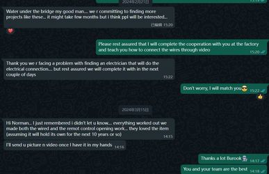 BurookHi Norman... I just remembered i didn't let u know.... everything worked out we made both the wired and the remot control opening work... they loved the item (assuming it will hold its own for the next 10 years or so)
 -
 KiranYes I don’t doubt you. Jutai is one of the most confident companies I came across in China
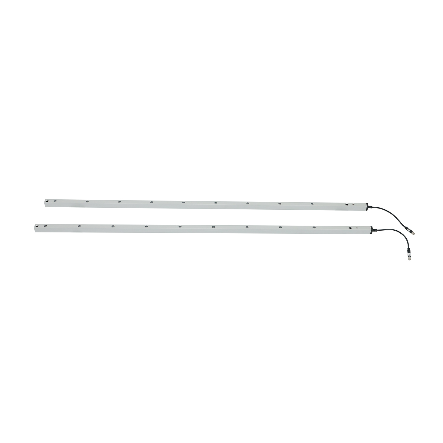
Photoelectric Safety Device for Automated Doors with Blanking Mode Function

| Place of Origin | China |
|---|---|
| Brand Name | JUTAI |
| Certification | CE |
| Model Number | CL20-8L |
| Document | CL05-8L User Manual.pdf |
| Minimum Order Quantity | 1 |
| Price | Negotiation |
| Packaging Details | Cartoon |
| Delivery Time | 5 - 8 working days |
| Payment Terms | T/T,L/C,D/A,D/P,Western Union,Paypal,,MoneyGram,Alipay |
| Supply Ability | 1000 pieces per month |
Product Details
| IP Rating | IP67 | Function | Blanking |
|---|---|---|---|
| Sensing Distance | 8m | Material | Aluminum Alloy |
| Feature | Corrosion Resistant | Power Voltage | DC12-24V |
| Operating Temperature | -20~60℃ | Operating Current | <50mA |
| Output | No/Nc, COM | Working Current | <20mA@DC12V-24V |
| Specification | 2000*21*15 Mm | ||
| Highlight | Photoelectric safety device for automated doors,IP67 blanking light curtain,Safety device with blanking mode |
||
Product Description
![]()
![]()
![]()
![]()
![]()
![]()
![]()
![]()
![]()
![]()
![]()
![]()
![]()
![]()
![]()
![]()
![]()
![]()
Recommended Products